

EOT CRANE DESIGN
Design of different parts and components of crane takes into consideration the following :
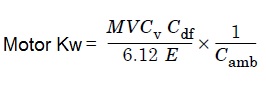
Motor - Heavy duty, reversible, fan cooled, foot mounted motors of required capacity are used to drive different mechanism of the crane. Hoist motor power is calculated by formula mentioned below:-
Gear Box - The speed reduction is obtained by using helical gearbox. The greaboxes are totally enclosed type and the lubrcation of gears & pinion is achieved by splash lubrication of the oil within the enclosure. For cross travel motion vertical gearbox can also be used. In case of three stage reduction vertical gearbox an oil pump is fitted to ensure lubrication of all gears. The service factor for gearbox is generally 1.7 times the torque rating of drive.
Coupling - Each motor is connected to its gearbox by a flexible coupling. The service factor for coupling is normally 1.7 times the torque rating of drive. For Hoisting mechanism output shaft of gearbox is connected to the drum through either geared coupling or barrel coupling. For CT or LT mechanism half geared couplings with floating shaft is provided between the wheel and the gearbox.
Brake- D.C. Electromagnetic brakes or D.C. Thruster brakes are provided to stop motion of different mechanism of the crane. Brake generally have rating of 1.5 times the calculated torque rating of drive. For hot metal handling cranes, hoist mechanism is provided with two brakes per motor.
Rope Drum- Drum for holding wire rope is fabricated from rolled steel plates or alternately made from cast steel. The diameter of drum is depended on the diameter of wire rope selected. The depth and pitch of grooves on drum is also dependent on the size of wire rope. Fabricated drum is stress relieved and machined for making grooves. Rope drum may be flanged at ends depending upon its design.
Sheaves/ Pulleys - During hoisting/ lowering operation of the crane, the wire rope rolls on sheaves. The number of sheaves is dependent upon the number of rope falls. The diameter of sheave is dependent on the diameter of wire rope. Equalizer sheave/ bar is provided on the trolley to maintain rope alignment. Sheaves mounted on trolley are called top block and sheaves mounted on hook assembly are called bottom block. Rope sheaves are made from either cast steel or are fabricated from rolled steel.
Wire Rope- The diameter of wire rope is calculated based on the load to be lifted and number of rope falls selected. The length of wire rope is dependent on the height of lift of crane. For cranes operating in hot ambience steel core rope is used. The strength/ grade of wire rope is selected from catalogue of wire rope manufacturers. The diameter of wire rope selected plays vital role in calculation of rope drum diameter & length.
Hook/ Hook Block- There are different types of hook such as C-Shank hook, Ramshorn hook, Laminated hook. Selection of hook type is dependent on the application of crane. Hook for hanging load are made from forged steel. Hook is assembled on the bottom block of crane. Hook block sheaves are provided with rope guard to retain the rope in the sheave groove.
Wheels- Wheels of crane are made from forged/ rolled/ cast steel. The diameter of wheel is calculated from the weight of the trolley and crane. For cranes of larger capacity the number of wheels are increased to reduce the wheel diameter. Cross Trolley wheels are double flanged. For Long Travel motion flange-less wheels with guide rollers are also used. Wheels are mounted on anti-friction roller bearing which is housed in `L' shaped bearing brackets.